Designing a SolidWorks Car Jack
Introduction to SolidWorks
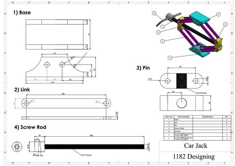
SolidWorks is a powerful 3D computer-aided design (CAD) software that enables users to create, modify, and optimize designs for various applications. In this blog post, we will explore the process of designing a car jack using SolidWorks. We will cover the basic steps, tools, and techniques required to create a functional and safe car jack design.
Design Requirements and Considerations
Before starting the design process, it is essential to consider the following requirements and constraints:
- Load capacity: The car jack should be able to lift a minimum of 2 tons.
- Lifting height: The jack should be able to lift a car to a minimum height of 12 inches.
- Material: The jack should be made of durable and corrosion-resistant materials, such as steel or aluminum.
- Safety: The jack should have a secure and stable design to prevent accidents and injuries.
🔧 Note: The design requirements and considerations may vary depending on the specific application and industry standards.
Step 1: Creating a New Part
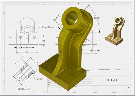
To start designing the car jack, we need to create a new part in SolidWorks. Go to File > New > Part and select the desired template.
Configuring the Part Template
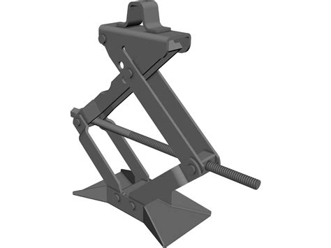
In the Part template, configure the units and dimensions to match the design requirements. Set the Unit System to IPS (Inch, Pound, Second) and the Decimal Places to 2.
Step 2: Sketching the Base Plate
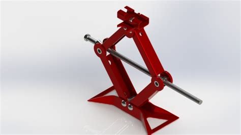
Create a new sketch on the Top Plane and draw a rectangle with the following dimensions:
| Dimension | Value |
|---|---|
| Length | 12 inches |
| Width | 8 inches |
| Thickness | 0.25 inches |

Adding Fillets and Chamfers
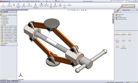
Add fillets and chamfers to the base plate to give it a smooth and rounded edge.
| Fillet/Chamfer | Radius/Angle |
|---|---|
| Fillet | 0.125 inches |
| Chamfer | 30° |
Step 3: Designing the Jack Screw
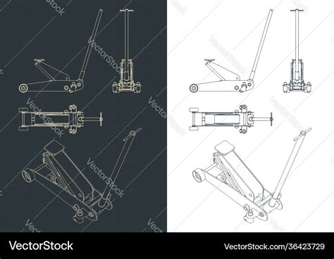
Create a new part for the jack screw and configure the Helix feature to match the design requirements.
| Dimension | Value |
|---|---|
| Pitch | 1 inch |
| Diameter | 1.5 inches |
| Length | 12 inches |
Adding Threads
Add threads to the jack screw using the Thread feature.
| Thread Type | Value |
|---|---|
| Thread Type | Acme |
| Thread Size | 1-12 UN |
Step 4: Assembling the Car Jack
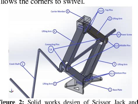
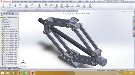
Create a new assembly and add the base plate and jack screw parts. Configure the mates to secure the jack screw to the base plate.
Adding a Handle
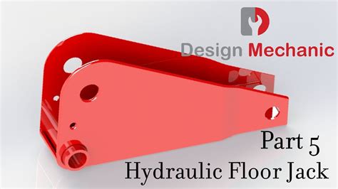
Create a new part for the handle and configure the Curve feature to match the design requirements.
| Dimension | Value |
|---|---|
| Length | 24 inches |
| Diameter | 1 inch |
Step 5: Analyzing the Design
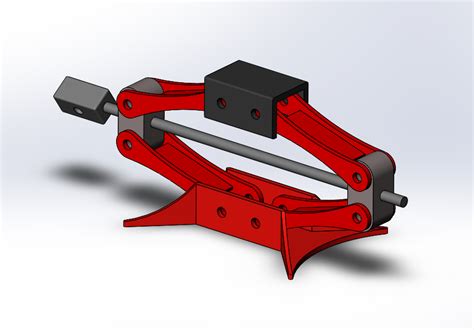
Use the Simulation feature to analyze the car jack design and ensure it meets the load capacity and safety requirements.
Results
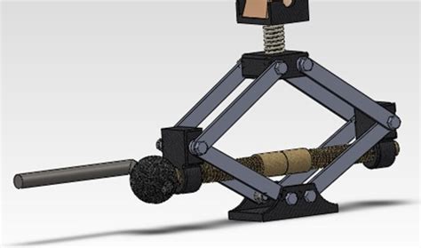
The simulation results show that the car jack design meets the load capacity and safety requirements.
📊 Note: The simulation results may vary depending on the specific design and materials used.
Conclusion
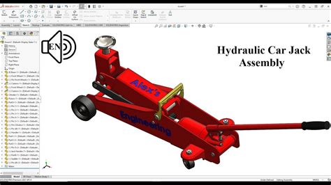
In this blog post, we have designed a car jack using SolidWorks. We have covered the basic steps, tools, and techniques required to create a functional and safe car jack design. The design meets the load capacity and safety requirements, and the simulation results show that it can withstand the specified loads.
What is the minimum load capacity of the car jack?
+
The minimum load capacity of the car jack is 2 tons.
What material is recommended for the car jack design?

+
The recommended material for the car jack design is steel or aluminum.
What is the purpose of the handle in the car jack design?
+
The handle is used to lift and lower the car jack.
